Define the cooling channels
Define all the cooling channels and identify inlets and outlets for each channel.
-
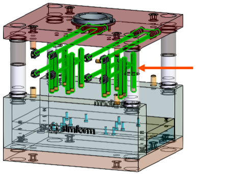
Use Ctrl-click to select all the cooling channels in the model as shown.
-
In the Channels card, click add
 to categorize the selections as channels.
Note that four channels are categorized in the Channels card.Since Detect Baffles Automatically is enabled by default, the software automatically categorizes the baffles included in the channel region.In the display window, note that the added channel color changes to gray and baffles to turquoise.
to categorize the selections as channels.
Note that four channels are categorized in the Channels card.Since Detect Baffles Automatically is enabled by default, the software automatically categorizes the baffles included in the channel region.In the display window, note that the added channel color changes to gray and baffles to turquoise.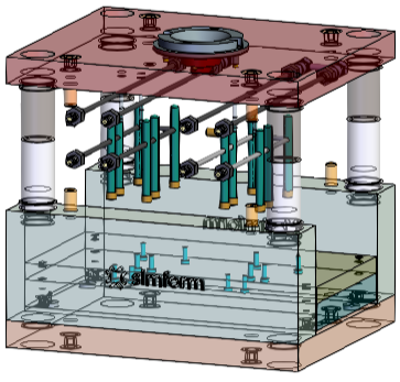
-
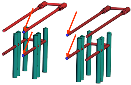
In the display window, for each of the four cooling channels, click the
corresponding inlet surface as shown in the following figure to designate it as
the inlet.
-
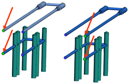
In the display window, for each of the four cooling channels, use Shift-click
to select the corresponding outlet surface as shown in the following figure to
designate it as the outlet.
-
Disable the Inlet/Outlet Selection Mode to define the
inlets and outlets for the channels.
The channel inlet and outlets are listed under the channels list. To remove an incorrect surface definition, click Remove Body
 .
.