Defining cooling channels
In a channel assessment job, if your model contains cooling channels, you must define the components that represent them so the solver can identify them.
You can categorize the cooling channels in your mold using one of the following approaches depending on the cooling channel definition in your model:
- If your mold contains cooling channels modeled as explicit physical bodies, you can categorize them using the Bodies selection mode. This mode lets you select the cooling channel bodies directly from the CAD model to assign them to the channel card category.
- If the cooling channels are drilled into your mold and are not modeled with physical bodies, you can extract them directly from the mold using the Faces selection mode. This mode lets you select a channel surface, and it automatically creates a channel body by connecting cylindrical channels that are connected to the selected surface with the same color.
To complete the channel definition, you specify the channel surfaces that define the inlet and outlet for the cooling liquid. You can use channels with one inlet and multiple outlets.
After you define the inlets and outlets, you can optionally specify a unique inlet temperature for each cooling channel. This allows more control over thermal behavior when different regions of the mold require different coolant conditions. If not specified, the solver uses the global inlet temperature value defined in the Inlet Temperature setting.
Categorizing baffles
The software allows you to automatically categorize the baffles included in the channel region. Baffles must be fully enclosed, except for the inlet and outlet. The software attempts to close any other gaps. In cases where the baffle geometry is unconventional or the baffle is not included in the channel selection, automatic detection may not categorize baffles correctly. In such cases, you can edit, repair, or identify the baffles manually.
The automatic baffle detection mode is enabled by default. You can disable it to prevent the automatic categorization of baffles.
Creating channels and baffles
You can create cooling channels directly in SimForm rather than importing them from your CAD model. You can either create a new channel or extend an existing one by adding another body. This lets you evaluate alternative cooling layouts without switching back to your CAD software.
SimForm supports creating only cylindrical channel geometries.
You can also add baffles to any existing cooling channel, whether you created it in SimForm or imported it. You can control their position and dimensions directly in the application interface.
When your simulation is complete, you can use the Download Channel/Baffle Geometries command on the results page to export the changes to the cooling channels and baffles as a CAD model that you can import into your CAD software. SimForm exports them in STEP files with STEP AP242 encoding type.
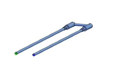
Channel color-coding guide
SimForm uses color-coding to help you verify channel definitions. The following table summarizes the color code used for channels.
| Color | Description | Example |
|---|---|---|
| Gray | Indicates a channel assigned to the Channels card. |
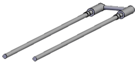 |
| Turquoise | Indicates a categorized baffle. |
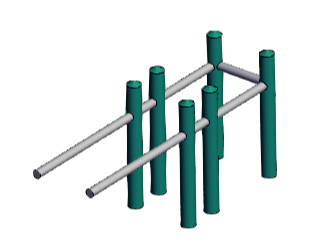 |
| Purple | Indicates a channel inlet surface. |
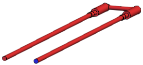 |
| Red | Indicates a channel with a defined inlet but no outlet. You must define the channel outlet. | |
| Green | Indicates a channel outlet surface. |
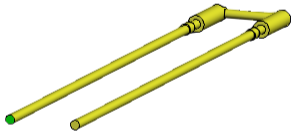 |
| Yellow | Indicates a channel with a defined outlet but no inlet. You must define the channel inlet. | |
| Blue | Indicates a channel with defined inlet and outlets. |
 |