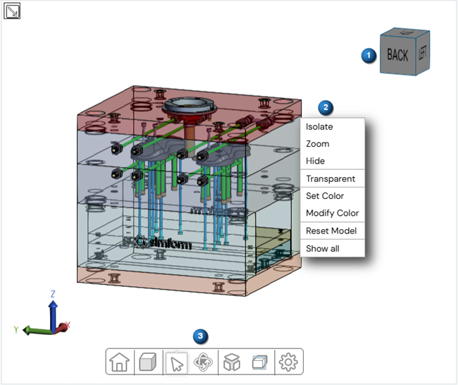
Setup display window options
The setup display window shows the CAD model in 3D and contains a toolbar for selection and view manipulation.
| Option | Description |
|---|---|
| Opens the model tree that displays the hierarchical structure of
the CAD model. It provides an organized view of the model's
components, allowing you to navigate, select, and manage individual
elements within the design. The model tree automatically selects bodies with the same name within the same parent assembly while keeping selections independent across different branches.
|
|
| (1) Model manipulation tool | Rotates the model around its geometrical center by clicking the cube face or rotating it. |
| (2) Right-click menu | |
| Appears when you right-click the display window background or a component in your design. | |
| Isolate | Available when you right-click a component. Displays only the selected components in the display window. |
| Zoom | Available when you right-click a component. Zooms in on the selected components. |
| Hide | Available when you right-click a component. Hides the selected components in the display window. |
| Transparent | Available when you right-click a component. Changes the component view to translucent. |
| Set Color | Available when you right-click a component. Changes the component's color to the one you select in the Color Picker window. |
| Unset Color | Restores the component's original color. |
| Modify Color | Opens the Color Picker window that lets you choose a custom color to apply to the selected components. |
| Reset Color | Restores the original view, showing hidden components and resetting colors. |
| Show all | Reveals all hidden components in the model. |
| Add body to | Available when you right-click on a component.
|
| Edit body | Available when you right-click a channel body. Opens the Edit Body window where you can modify the diameter and length values of the channel. |
| Remove body | Available when you right-click a created channel body. Removes the selected body from the cooling channel. |
| Add baffle | Available when you right-click an existing channel body. Opens the Create Baffle window where you define the baffle dimensions and add it to your cooling channel. |
| Edit baffle | Available when you right-click a baffle. Opens the Edit Baffle window where you can modify the diameter and length values of the baffle. |
| Remove baffle | Available when you right-click a created baffle. Removes the selected baffle from the cooling channel. |
| Hide/Show Recommendations | Appears for the channel assessment job type when you import the recommendation results from a solved
channel recommender job. Controls the visibility of the recommendation results. |
Toolbar options
The following table lists the options for the selection and view manipulation toolbar (3).
| Option | Description |
|---|---|
| Resets the model view to its default position and orientation. | |
| Display mode menu | |
Displays the model with solid surfaces and visible
edges.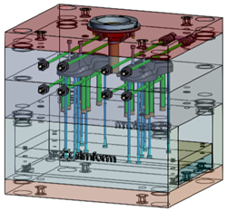 |
|
Displays the model with solid surfaces only, hiding all
edges.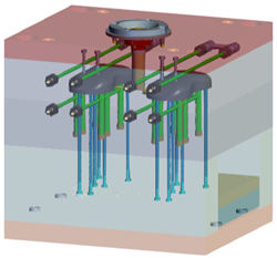 |
|
Shows only visible edges, hiding lines that are behind
surfaces. |
|
Displays all the model edges without surfaces.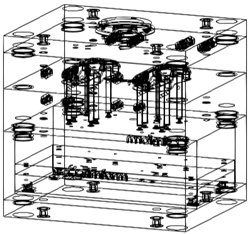 |
|
Displays the model with semi-transparent surfaces.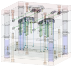 |
|
| Selection menu | |
| Lets you select individual components in your model. | |
| Lets you select multiple components in your model by defining a selection area. | |
| Measures the length of a selected edge. | |
| Measures the straight-line distance between two selected points. | |
| Calculates the angle between two selected faces. | |
| Measures the shortest distance between two selected faces. | |
| Camera navigation menu | |
| Rotates the model view sideways, up, and down around your perspective. | |
| Rotates the model around the Z vertical axis. | |
| Rotates the model freely around its geometric center for 360° viewing from any angle. | |
| Explode menu | |
Opens a slider that lets you create an exploded view of your
model by separating its components.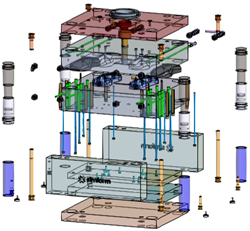 |
|
| Cutting planes menu | |
| Displays a cutting plane along the Z-axis that you can select and translate to examine a cutaway of the model. | |
| Displays a cutting plane along the Y-axis that you can select and translate to examine a cutaway of the model. | |
| Displays a cutting plane along the X-axis that you can select and translate to examine a cutaway of the model. | |
| Displays a cutting plane on the selected face that you can select and translate to examine a cutaway of the model. | |
| Hides or shows the cutting planes of your model. | |
| Removes all cutting planes from the model view. | |
| Settings menu | |
| Opens the display setting window that lets you edit the display settings, such as the background and measurement colors and the Walk option parameters. | |